Featured post

Top 5 books to refer for a VHDL beginner

VHDL (VHSIC-HDL, Very High-Speed Integrated Circuit Hardware Description Language) is a hardware description language used in electronic des...

Friday 15 July 2011

Polar Satellite Launch Vehicle (PSLV-C17) Successfully Launches GSAT - 12 Satellite

India's Polar Satellite Launch Vehicle (PSLV-C17) successfully launched GSAT-12 communication satellite today (July 15, 2011) from Satish Dhawan Space Centre (SDSC) SHAR, Sriharikota. The launch of PSLV-C17 was the eighteenth successive successful flight of PSLV.

After a smooth countdown of 53 hours, the vehicle lifted-off from the Second Launch Pad at the opening of the launch window at 16:48 hrs (IST). After about 20 minutes of flight time, GSAT-12 was successfully injected into sub-Geosynchronous Transfer Orbit (sub-GTO) with a perigee of 284 km and an apogee of 21,020 km with an orbital inclination of 17.9 deg.

The preliminary flight data indicates that all major flight events involving stage ignition and burnouts, performance of solid and liquid stages, indigenously developed advanced mission computers and telemetry systems have performed well.

ISRO Telemetry Tracking and Command Network (ISTRAC)'s ground station at Biak, Indonesia acquired the signals from GSAT-12 immediately after the injection of the satellite. The solar panels of the satellite were deployed automatically. Initial checks on the satellite have indicated normal health of the satellite.

India's Advanced Communication Satellite GSAT-8 Launched Successfully

India's advanced communication satellite, GSAT-8, was successfully launched at 02:08 hrs IST today (May 21, 2011) by the Ariane-V launch vehicle of Arianespace from Kourou. French Guiana. Ariane V placed GSAT-8 into the intended Geosynchronous Transfer Orbit (GTO) of 35,861 km apogee and 258 km perigee, with an orbital inclination of 2.503 deg with respect to equator.gsat-8
ISRO's Master Control Facility (MCF) at Hassan in Karnataka acquired the signals from GSAT-8 satellite immediately after the injection. Initial checks on the satellite have indicated normal health of the satellite. The satellite was captured in three-axis stabilization mode. Preparations are underway for the firing of 440 Newton Liquid Apogee Motor (LAM) during the third orbit of the satellite on May 22, 2011 at 03:58 hrs IST as a first step towards taking the satellite to its geostationary orbital home.

About GSAT-8:

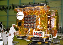
GSAT-8, India’s advanced communication satellite, is a high power communication satellite being inducted in the INSAT system. Weighing about 3100 Kg at lift-off, GSAT-8 is configured to carry 24 high power transponders in Ku-band and a two-channel GPS Aided Geo Augmented Navigation (GAGAN) payload operating in L1 and L5 bands.
The 24 Ku band transponders will augment the capacity in the INSAT system. The GAGAN payload provides the Satellite Based Augmentation System (SBAS), through which the accuracy of the positioning information obtained from the GPS Satellite is improved by a network of ground based receivers and made available to the users in the country through the geostationary satellites.

Mission : Communication

Weight : 3093 kg (Mass at Lift – off) 1426 kg (Dry Mass)

Power : Solar array providing 6242 watts three 100 Ah Lithium Ion batteries

Physical Dimensions : 2.0 x 1.77 x 3.1m cuboid

Propulsion : 440 Newton Liquid Apogee Motors (LAM) with mono Methyl Hydrazine (MMH) as fuel and Mixed oxides of Nitrogen (MON-3) as oxidizer for orbit raising.

Stabilizations : 3-axis body stabilized in orbit using Earth Sensors, Sun Sensors, Momentum and Reaction Wheels, Magnetic Torques and eight 10 Newton and eight 22 Newton bipropellant thrusters

Antennas : Two indigenously developed 2.2 m diameter transmit/receive polarization sensitive dual grid shaped beam deployable reflectors with offset-fed feeds illumination for Ku-band; 0.6 m C-band and 0.8x0.8 sq m L-band helix antenna for GAGAN

Launch date : 21-May-11

Launch site : Kourou, French Guiana

Launch vehicle : Ariane-5 VA-202

Orbit : Geosynchronous (55° E)

Mission life : More Than 12 Years

Saturday 9 July 2011

Intel’s Haswell Microarchitecture

Haswell is the codename for a processor microarchitecture to be developed by Intel's Oregon team as successor to the Sandy Bridge architecture.Haswell will use a 22 nm process.CPUs based on the Haswell microarchitecture are expected to be released in 2013. There are currently no details regarding this microarchitecture's development.

Haswell is confirmed to have:

  • A 22 nm process.
  • 3D tri-gate transistors.
  • Advanced Vector Extensions 2(AVX2) instruction set (or Haswell New Instructions)

Haswell is expected to have:

  • FMA3 instructions.
  • A 14 stage pipeline.
  • A new cache design.
  • Up to 8 cores available.
  • New advanced power-saving system.
  • 64 kB data + 64 kB instruction L1 cache per core, 8-way associativity
  • 1 MB L2 cache per core, 8-way associativity.
  • Up to 32 MB L3 cache shared by all cores, 16-way associativity.

Sandy Bridge

Sandy Bridge is the codename for a processor microarchitecture developed by Intel's Israel Development Center. Development began in 2005 targeting the 32 nm process. The codename for this architecture was previously "Gesher" (which means "bridge" in Hebrew). Sandy Bridge processors were first released on January 9, 2011. Intel first previewed a Sandy Bridge processor with A1 stepping at 2 GHz during the Intel Developer Forum in 2009. The yet-to-be released 22 nm die shrink of Sandy Bridge has the codename Ivy Bridge.

Sandy Bridge is one of the most ambitious and aggressive microprocessors designed at Intel. The degree of complexity and integration is simply astounding. It combines a new CPU microarchitecture, a new graphics microarchitecture, each of which is a substantial departure from the previous generation. On top of that, the chip level integration has taken a huge step forward; with a much more complex system agent and a new L3 cache and ring interconnect shared by all the components. Coherent communication between the CPU and GPU in Sandy Bridge is a substantial advance for the industry and presents many opportunities. Dealing with all these different facets of Sandy Bridge in a single discussion is impossible given the scope of changes.

Sandy Bridge is a fundamentally new microarchitecture for Intel. While it outwardly resembles Nehalem and the P6, it is internally far different. The essence of an out-of-order microarchitecture is tracking, re-ordering, renaming and dynamically scheduling operations to achieve the limit of data flow. Nehalem and Westmere rely on the same mechanisms that date back to the original P6. Sandy Bridge changes the underlying out-of-order engine and uses the more efficient approach taken by the EV6 and P4. That one change alone qualifies Sandy Bridge as a different breed entirely from the P6. But, there are changes in almost every other aspect of the design. The uop cache is a huge improvement for the front-end, largely by eliminating many of the vagaries of x86 fetch and decode. The implementation is quite clever and achieves many of the aims of the P4’s trace cache, but in a far more efficient and reliable manner. AVX improves execution throughput and most importantly, the more flexible memory pipelines benefit almost all workloads.

In the coming year, three new microarchitectures will grace the x86 world. This abundance of new designs is exciting; especially since each one embodies a different philosophy. At the high-end, Sandy Bridge focuses on efficient per-core performance, while Bulldozer explicitly trades away some per-core performance for higher aggregate throughput. AMD’s Bobcat takes an entirely different road, emphasizing low-power, but retaining performance. In contrast, Intel’s Atom is truly intended to reach the most power sensitive applications. The two high-end microarchitectures, Sandy Bridge and Bulldozer, are shown below in Figure 7. Note that each Bulldozer module would include two integer cores while sharing the front-end and floating point cluster. Also, the floating point cluster in Bulldozer does not directly access memory, instead it uses the memory pipelines in the two attached cores, which then forward results to the FP cluster.

intels_sandy_bridge_microarchitecture

With the limited details, it is hard to predict the chip level performance for products based on these two microarchitectures. Frequencies are still undisclosed, or have yet to be determined and the client and server products will be rather different. In the case of Sandy Bridge, the clock speed should be in the same vicinity as Nehalem or Westmere – however, Bulldozer is clearly intended to run faster, but the frequency will probably be dictated by power consumption. For Bulldozer, there are also numerous details on the integration (e.g. L3 cache design, snoop filter) that are undisclosed. Nonetheless, it is possible to make some educated estimates about the performance of the two microarchitectures.

In looking at the two designs, it is sensible to compare a multi-threaded Sandy Bridge core to a Bulldozer module and separately consider single threaded operation as a special case. Both support two threads although the resources are very different. At a high level, Sandy Bridge shares everything between threads, whereas Bulldozer flexibly shares the front-end and floating point units, while separating the integer cores.

A Sandy Bridge core should have substantially higher performance than a Bulldozer module across the board for single threaded or lightly threaded code. It will also have an additional advantage for floating point workloads that use AVX, (e.g. numerical analysis for finance, engineering). With AVX, each Sandy Bridge core can have up to 2X the FLOP/cycle of a Bulldozer module, although they would be at parity if the code is compiled to use AMD’s FMA4 (e.g. via OpenCL). FMA4 will be relatively rare because, while elegant, it is likely to be a historical footnote for x86, supplanted by Intel’s FMA3. For software still relying on SSE, the difference between the two should be minimal. In comparison, Bulldozer will favor heavily multi-threaded software. Each module has twice the memory pipelines and slightly more resources (e.g. retirement queue/ROB entries, memory buffers) than a single Sandy Bridge core with two threads, so Bulldozer should do very well in many highly parallel integer workloads that exercise the memory pipelines.

In many ways, the strengths of Sandy Bridge reflect the intentions of the architects. Sandy Bridge is first and foremost a client microprocessor – which requires single threaded performance. Bulldozer is firmly aimed at the server market, where sacrificing single threaded performance for aggregate throughput is an acceptable decision in some cases. Perhaps in future articles, we can examine the components of performance in greater detail (e.g. frequency, IPC, etc.), but for now, high level guidance seems appropriate – given the level of disclosure from both vendors.

Ultimately, we will be waiting for real hardware to see how the Sandy Bridge client performs in the wild. The base clocks, realistic turbo frequencies and power consumption will all be very interesting to observe – and help estimate server performance as well. For now the hardware certainly looks promising and while we await products, we’ll have other reports on different aspects of Sandy Bridge to keep us occupied. The design team certainly deserves a round of congratulations for a job well done, redoing the microarchitecture from the ground up while tackling all the integration challenges.

Intel Nehalem Architecture

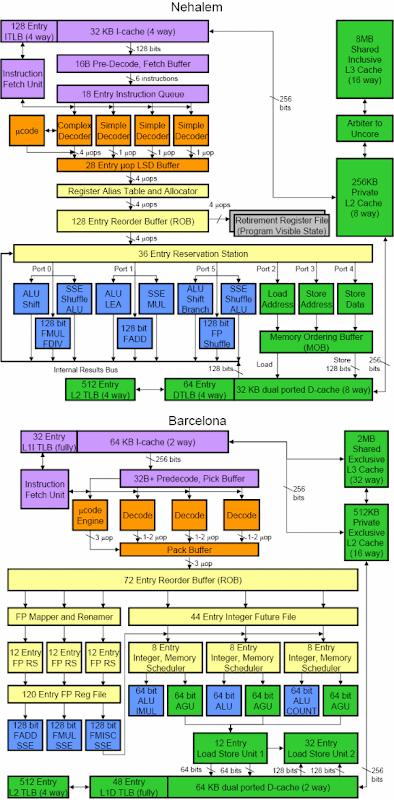
Nehalem is the codename for an Intel processor microarchitecture, successor to the Core microarchitecture. Nehalem processors use the 45 nm process. A preview system with two Nehalem processors was shown at Intel Developer Forum in 2007. The first processor released with the Nehalem architecture was the desktop Core i7, which was released in November 2008.

Nehalem, a recycled codename, refers to a completely different architecture from Netburst, although Nehalem still has some things in common with NetBurst. Nehalem-based microprocessors utilize higher clock speeds and are more energy-efficient than Penryn microprocessors. Hyper-Threading is reintroduced along with an L3 Cache missing from most Core-based microprocessors.

Intel_Nehalem_architecture

Tuesday 5 July 2011

Application of Synchronous “up/down” counters

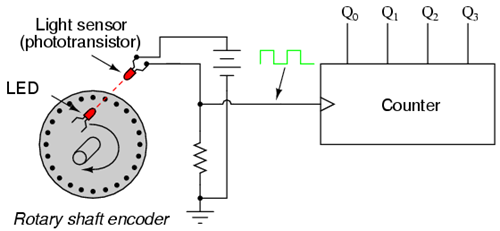
Up/down counter circuits are very useful devices. A common application is in machine motion control, where devices called rotary shaft encoders convert mechanical rotation into a series of electrical pulses, these pulses "clocking" a counter circuit to track total motion:

Application_of_synchronous_up_down_counter1

As the machine moves, it turns the encoder shaft, making and breaking the light beam between LED and phototransistor, thereby generating clock pulses to increment the counter circuit. Thus, the counter integrates, or accumulates, total motion of the shaft, serving as an electronic indication of how far the machine has moved. If all we care about is tracking total motion, and do not care to account for changes in the direction of motion, this arrangement will suffice. However, if we wish the counter to increment with one direction of motion and decrement with the reverse direction of motion, we must use an up/down counter, and an encoder/decoding circuit having the ability to discriminate between different directions.

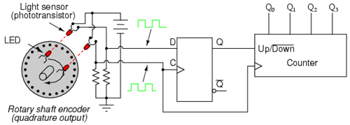
If we re-design the encoder to have two sets of LED/phototransistor pairs, those pairs aligned such that their square-wave output signals are 90o out of phase with each other, we have what is known as a quadrature output encoder (the word "quadrature" simply refers to a 90o angular separation). A phase detection circuit may be made from a D-type flip-flop, to distinguish a clockwise pulse sequence from a counter-clockwise pulse sequence:

Application_of_synchronous_up_down_counter2

When the encoder rotates clockwise, the "D" input signal square-wave will lead the "C" input square-wave, meaning that the "D" input will already be "high" when the "C" transitions from "low" to "high," thus setting the D-type flip-flop (making the Q output "high") with every clock pulse. A "high" Q output places the counter into the "Up" count mode, and any clock pulses received by the clock from the encoder (from either LED) will increment it. Conversely, when the encoder reverses rotation, the "D" input will lag behind the "C" input waveform, meaning that it will be "low" when the "C" waveform transitions from "low" to "high," forcing the D-type flip-flop into the reset state (making the Q output "low") with every clock pulse. This "low" signal commands the counter circuit to decrement with every clock pulse from the encoder.

This circuit, or something very much like it, is at the heart of every position-measuring circuit based on a pulse encoder sensor. Such applications are very common in robotics, CNC machine tool control, and other applications involving the measurement of reversible, mechanical motion.

4-bit Synchronous “down” counter

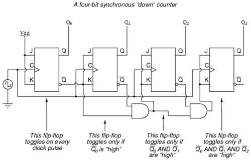
To make a synchronous "down" counter, we need to build the circuit to recognize the appropriate bit patterns predicting each toggle state while counting down. Not surprisingly, when we examine the four-bit binary count sequence, we see that all preceding bits are "low" prior to a toggle (following the sequence from bottom to top):

Since each J-K flip-flop comes equipped with a Q' output as well as a Q output, we can use the Q' outputs to enable the toggle mode on each succeeding flip-flop, being that each Q' will be "high" every time that the respective Q is "low:"

4_bit_Synchronous_down_counter

Links :

Get free daily email updates!

Follow us!

4-bit Synchronous “up” Counter

Examining the four-bit binary count sequence, another predictive pattern can be seen. Notice that just before a bit toggles, all preceding bits are "high:"

This pattern is also something we can exploit in designing a counter circuit. If we enable each J-K flip-flop to toggle based on whether or not all preceding flip-flop outputs (Q) are "high," we can obtain the same counting sequence as the asynchronous circuit without the ripple effect, since each flip-flop in this circuit will be clocked at exactly the same time:

4_bit_Synchronous_up_counter

The result is a four-bit synchronous "up" counter. Each of the higher-order flip-flops are made ready to toggle (both J and K inputs "high") if the Q outputs of all previous flip-flops are "high." Otherwise, the J and K inputs for that flip-flop will both be "low," placing it into the "latch" mode where it will maintain its present output state at the next clock pulse. Since the first (LSB) flip-flop needs to toggle at every clock pulse, its J and K inputs are connected to Vcc or Vdd, where they will be "high" all the time. The next flip-flop need only "recognize" that the first flip-flop's Q output is high to be made ready to toggle, so no AND gate is needed. However, the remaining flip-flops should be made ready to toggle only when all lower-order output bits are "high," thus the need for AND gates.

Links :

Synchronous “up/down” Counter

We can build a counter circuit with selectable between "up" and "down" count modes by having dual lines of AND gates detecting the appropriate bit conditions for an "up" and a "down" counting sequence, respectively, then use OR gates to combine the AND gate outputs to the J and K inputs of each succeeding flip-flop:

4_bit_Synchronous_up_down_counter

This circuit isn't as complex as it might first appear. The Up/Down control input line simply enables either the upper string or lower string of AND gates to pass the Q/Q' outputs to the succeeding stages of flip-flops. If the Up/Down control line is "high," the top AND gates become enabled, and the circuit functions exactly the same as the first ("up") synchronous counter circuit shown in this section. If the Up/Down control line is made "low," the bottom AND gates become enabled, and the circuit functions identically to the second ("down" counter) circuit shown in this section.

To illustrate, here is a diagram showing the circuit in the "up" counting mode (all disabled circuitry shown in grey rather than black):

4_bit_Synchronous_up_down_counter_count_up_mode 

Here, shown in the "down" counting mode, with the same grey coloring representing disabled circuitry:

4_bit_Synchronous_up_down_counter_count_down_mode

Links:

Different type of synchronous counters

A synchronous counter, in contrast to an asynchronous counter, is one whose output bits change state simultaneously, with no ripple. The only way we can build such a counter circuit from J-K flip-flops is to connect all the clock inputs together, so that each and every flip-flop receives the exact same clock pulse at the exact same time.

In electronics, synchronous counters can be implemented quite easily using register-type circuits such as the flip-flop, and a wide variety of classifications exist:

Binary counters

Binary counters are the simplest form of counters. An N-bit binary counter counts from 0 to (2N - 1) and back to 0 again.

binary_synchronous_counter


Links:

  • Different types of counters
  • Up/down counters
  • Loadable counters
  • BCD counters
  • Ring counters
  • Johnson counters

  • Why “synchronous”?

    • The difference between asynchronous and synchronous counters.

    In an asynchronous counter, an external event is used to directly SET or CLEAR a flip-flop when it occurs. In a synchronous counter however, the external event is used to produce a pulse that is synchronised with the internal clock. An example of an asynchronous counter is a ripple counter. Each flip-flop in the ripple counter is clocked by the output from the previous flip-flop. Only the first flip-flop is clocked by an external clock. Below is an example of a 4-bit ripple counter.

    4_bit_asynchronous_counter

    • Dangers of asynchronous counters.

    Although the asynchronous counter is easier to implement, it is more "dangerous" than the synchronous counter. In a complex system, there are many state changes on each clock edge, and some IC's (integrated circuits) respond faster than others. If an external event is allowed to affect a system whenever it occurs, a small percentage of the time it will occur near a clock transition, after some IC's have responded, but before others have. This intermingling of transitions often causes erroneous operations. What is worse, these problems are difficult to test for and difficult to foresee because of the random time difference between the events.


    Links:

    Monday 4 July 2011

    Why do we need counters ?

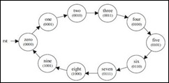
    In a digital circuit, counters are used to do 3 main functions: timing, sequencing and counting.

    A timing problem might require that a high-frequency pulse train, such as the output of a 10-MHz crystal oscillator, be divided to produce a pulse train of a much lower frequency, say 1 Hz. This application is required in a precision digital clock, where it is not possible to build a crystal oscillator whose natural frequency is 1 Hz.

    State_machine_of_a_BCD_CounterA sequencing problem would arise if, for instance, it became necessary to apply power to various components of a large machine in a specific order. The starting of a rocket motor is an example where the energizing of fuel pumps, ignition, and possibly explosive bolts for staging must follow a critical order.

    Measuring the flow of auto traffic on roadway is an application in which an event (the passage of a vehicle) must increment a tally. This can be done automatically with an electronic counter triggered by a photocell or road sensor. In this way, the total number of vehicles passing a certain point can be counted.

    Links:

    Synchronous Counter

    The purpose of writing this is to collate information on Digital Synchronous Counters. Particular emphasis was placed on the following areas :

    1. Types of Synchronous Counters and How they work

    2. Fast Counter Techniques

    3. Implementation of Counters :

    4. Dedicated Hardware and Alternative Devices

    According to the Oxford Encyclopædic Dictionary:

    synchronous adj. existing or occurring at the same time.

    counter n. an apparatus used for counting. || a person or thing that counts.

    So a "synchronous counter" should mean "a person, thing or apparatus that counts at the same time" ?!?! Hmmm...

    Let us take a look at the definition given by the IBM Dictionary of Computing instead.

    synchronous (1) Pertaining to two or more processes that depend upon the occurrence of specific events such as common timing signals. (2) Occurring with a regular or predictable time relationship.

    counter (1) A functional unit with a finite number of states each of which represents a number that can be, upon receipt of an appropriate signal, increased by unity or by a given constant. This device is usually capable of bringing the represented number to a specified value; for example zero.

    So a "synchronous counter" is actually a functional unit with a certain number of states, each representing a number which can be increaced or decreased upon receiving an appropriate signal (e.g. a rising edge pulse), and is usually used to count to, or count down to zero from, a specified number N.

    ... and what it "really" means. OK! Enough of dictionary definitions.

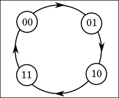
    Basically, any sequential circuit that goes through a prescribed sequence of states upon the application of input pulses is called a counter. The input pulses, called count pulses, may be clock pulses or they may originate from an external source and may occur at prescribed intervals of time or at random. The sequence of states in a counter may follow a binary count or any other sequence.

    Counter_State_Maching


    Read More

    Sunday 3 July 2011

    VLSI FPGA Projects Topics Using VHDL/Verilog

      1. 8-bit Micro Processor

      2. RISC Processor in VLDH

      3. Floating Point Unit

      4. LFSR - Random Number Generator

      5. Versatile Counter

      6. RS232 interface

      7. I2C Slave

      8. 8b10b Encoder/Decoder

      9. Floating Point Adder and Multiplier

      10. Progressive Coding For Wavelet-Based Image Compression

      11. An Area-Efficient Universal Cryptography Processor for Smart Cards

      12. FPGA Based Power Efficient Channelizer for Software Defined Radio

      13. Implementation of IEEE 802.11a WLAN baseband Processor using FPGA with Verilog/VHDL code

      14. FPGA Implementation of USB Transceiver Macrocell Interface with Usb2.0 Specifications

      15. Design of a Multi-Mode Receive Digital-Front-End for Cellular Terminal RFIC

      16. Superscalar Power Efficient Fast Fourier Transform FFT Architecture

      17. High-Speed Architecture for Reed-Solomon Decoder/Encoder

      18. Fault Secure Encoder and Decoder for Nano-memory Applications

      19. Implementation Huffman Coding For Bit Stream Compression In Mpeg – 2

      20. Implementation of Hash Algorithm Used for Cryptography And Security

      21. Implementation of Scramblers and Descramblers in Fiber Optic Communication Systems – SONET and OTN

      22. Implementation of Matched Filters Frequency Spectrum in Code Division Multiple Access (CDMA) System and its Implementation

      23. High Definition HDTV Data Encoding and Decoding using Reed Solomon Code

      24. Design & Implementation of Noise / Echo canceler using FPGA with Verilog/VHDL

      25. A VLSI Architecture for Visible Watermarking In A Secure Still Digital Camera (S2dc) Design

      26. FPGA-Based Architecture for Real Time Image Feature Extraction

      27. Implementation of Lossless Data Compression and Decompression using (Parallel Dictionary Lempel Ziv Welch) PDLZW Algorithm

      28. 8/16/32 Point Fast Fourier Transform Algorithm using FPGA with Verilog/VHDL

      29. VLSI Implementation of Booths Algorithm using FPGA with Verilog/VHDL

      30. Design of a Multi-Mode Receive Digital-Front-End for Cellular Terminal RFICs

      31. VLSI implementation of Cascaded-Integrator-Comb Filter

      32. VLSI implementation of Wave-Digital-Filters

      33. VLSI implementation of Notch filters

      34. VLSI implementation of fractional sample rate converter (FSRC) and corresponding converter architecture

      35. VLSI implementation of canonical Huffman encoder/decoder algorithm using FPGA with Verilog/VHDL code

      36. VLSI implementation of RC5 Encryption/Decryption Algorithm

      37. VLSI implementation of Steganography using FPGA with Verilog/VHDL code

      38. VLSI implementation of 16 Bit fixed point DSP Processor using FPGA with Verilog/VHDL

      39. VLSI Implementation of Address Generation Coprocessor

      40. VLSI Implementation of AHDB (Adaptive Huffman Dynamic Block) Algorithm

      41. Implementation of LZW Data Compression Algorithm.

      42. A Low Power VLSI Implementation for JPEG2000 Codec using FPGA with Verilog/VHDL

      43. A Verilog Implementation of Built In Self Test of UART

      44. Fuzzy based PID Controller using VHDL for Transportation Application

      45. VLSI Architecture and FPGA Prototyping of a Digital Camera for Image Security and Authentication

      46. Scalable multi gigabit pattern matching for packet inspection

      47. An FPGA-based Architecture for Real Time Image Feature Extraction

      48. Synchronization in Software Radios – Carrier and Timing Recovery Using FPGAs

      49. Optimized Software Implementation of a Full-Rate IEEE 802.11a Compliant Digital Baseband Transmitter on a Digital Signal Processor

      50. High-Speed Booth Algorithm Encoded Parallel Multiplier Design

      51. Implementation of IEEE 802.11a WLAN Baseband Processor

      52. MPEG-4 AVClH.264 Transform Coding Design using FPGA with Verilog/VHDL

      53. FPGA based Generation of High Frequency Carrier for Pulse Compression using CORDIC Algorithm

      54. Watermarking in a Secure Still Digital Camera Design

      55. DCT/IDCT Algorithms Implemented in FPGA Chips for Real-Time Image Compression

      56. VLSI Architecture and FPGA Prototyping of a Digital Camera for Image Security and Authentication

      57. Robust Image Watermarking Based on Multiband Wavelets and Empirical Mode Decomposition

      58. A VLSI Architecture for Visible Watermarking in a Secure Still Digital Camera (S2DC) Design

      59. VLSI Design & Implementation of Cryptography AES/DES Encryption Algorithm using FPGA with Verilog/VHDL code

      60. VLSI Design & Implementation of Viterbi Algorithm-Encoder/Decoder using FPGA with Verilog/VHDL code

      61. VLSI Design & Implementation of DDRR Algorithm using FPGA with Verilog/VHDL code

      62. VLSI Design & Implementation of Dynamic/Deficit Round Robin Algorithm using FPGA with Verilog/VHDL code

      63. VLSI Design & Implementation of Watermarking Algorithm using FPGA with Verilog/VHDL code

      64. VLSI Design & Implementation of Secure transmitting and receiving text data in communication systems using FPGA with Verilog/VHDL code

      65. VLSI Design & Implementation of UART Asynchronous Transmitter/Receiver using FPGA with Verilog/VHDL code

      66. VLSI Design & Implementation of RS-232 Transmitter/Receiver using FPGA with Verilog/VHDL code

      67. VLSI Design & Implementation of Asynchronous Serial controller using FPGA with Verilog/VHDL code

      68. VLSI Design & Implementation of Universal Serial Bus USB Device Controller using FPGA with Verilog/VHDL code

      69. VLSI Design & Implementation of GPS-GSM based Home Automation System using FPGA with Verilog/VHDL code

      70. VLSI Design & Implementation of 16/32/64-bit Low Power RISC/CISC Processor using FPGA with Verilog/VHDL code

      71. VLSI Design & Implementation of Multichannel I2S Audio Controller using FPGA with Verilog/VHDL code

      72. VLSI Design & Implementation of Asynchronous FIFO using FPGA with Verilog/VHDL code

      73. VLSI Design & Implementation of AHB Master/Slave using FPGA with Verilog/VHDL code

      74. VLSI Design & Implementation of AMBA AHB to PVCI Bridge using FPGA with Verilog/VHDL code

      75. VLSI Design & Implementation of Huffman Encoder/Decoder using FPGA with Verilog/VHDL code

      76. VLSI Design & Implementation of Programmable 16-Tap FIR Filter using FPGA with Verilog/VHDL code

      77. VLSI Design & Implementation of 2-D Convolution Engine using FPGA with Verilog/VHDL code

      78. VLSI Design & Implementation of VGA/LCD Controller using FPGA with Verilog/VHDL code

      79. VLSI Design & Implementation of JTAG TAP controller using FPGA with Verilog/VHDL code

      80. VLSI Design & Implementation of Booth Multiplier using FPGA with Verilog/VHDL code

      81. VLSI Design & Implementation of Pipeline JPEG Encoder using FPGA with Verilog/VHDL code

      82. VLSI Design & Implementation of Cyclic Redundancy Check ECRC/LCRC Error Check using FPGA with Verilog/VHDL code

      83. VLSI Design & Implementation of Vehicle Tracking & Safety System using FPGA with Verilog/VHDL code

      84. VLSI Design & Implementation of Low Power FIR Filter using FPGA with Verilog/VHDL code

      85. VLSI Design & Implementation of Pattern Generator using FPGA with Verilog/VHDL code

      86. VLSI Design & Implementation of PCI Express using FPGA with Verilog/VHDL code

      87. VLSI Design & Implementation of Highspeed USB 2.0/Superspeed USB 3.0 Transmitter and Receiver using FPGA with Verilog/VHDL code

      88. VLSI Design & Implementation of Wishbone Controller using FPGA with Verilog/VHDL code

      89. VLSI Design & Implementation of PVCI Master/Slave using FPGA with Verilog/VHDL code
    Get free daily email updates!

    Follow us!