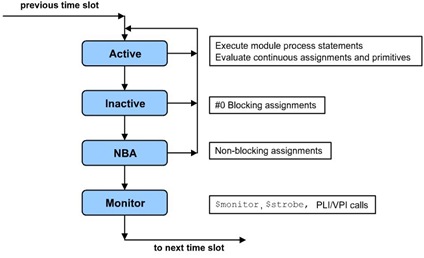
A simulation timeslot is divided into ordered regions to provide a predictable interaction between design constructs. Verilog event scheduler has four regions for each simulation time as Fig 1.
 Fig 1: Active region is for executing process statements; Inactive region is for executing process statements postponed with a “#0″ procedural delay; NBA region is for updating non-blocking assignments; Monitor region is for executing $monitor and $strobe and for calling user routines registered gor execution during this read-only region.
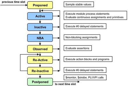
SystemVerilog adds regions to provide a predictable interaction between assertions, design code and testbench code.
 Fig 2: Preponed region is fora smapling signal values before anything in the time slice changes their values; additional observed region is for assertion evaluation. Re-Active and Re-Inactive regions is for executing assertion action blocks and testbenchh programs; Postponed region is for system tasks that record signal values at the end of the time slice.
SV introduces new verification blocks:
— Program
To have clear sepration between testbench and design, SV introdueces program block, which contains full environment for testbench. It is intended to reduce user-induced races. It executes in the Re-Active region.
— Final
“Final” block is used to print summary information in log file at the end of simulation. It executes at the end of the simulation (after explicit or implicit call to $finish) without delays.
e.g.
program asic_with_ankit;
  int error, warning;
  initial begin
  //Main program activities…..
  end
  final begin
  $display (“Test is done with %d errors and %d warnings”, error, warning);
  end
endprogram
— clocking blocks
A clocking block identifies clock signals and captures the timing and synchronization requirements of the blocks being modeled. It supports following features
– Input sampling
– Synchronous events
– Synchronous drives
e.g.
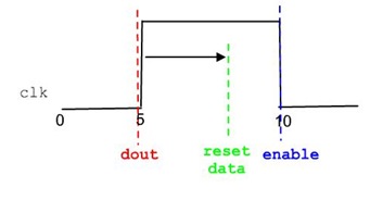
clocking cb @(posedge clk);
  default input #1step //default timing skew for inputs/outputs
          output #3;
  input dout;
  output reset, data;
  output negedge enable;
endclocking
Inputs are sampled at clock edge and outputs are driven at clock edge. Input skew designates sample time before clock edge and output skew designates driving time after the clocking event.


No comments:
Post a Comment
Please provide valuable comments and suggestions for our motivation. Feel free to write down any query if you have regarding this post.